Intro
This will be a fairly short post on how to interface the Sensirion SPS30 with a Catena 4610 LoRaWAN node dev board.
The Catena board is based on the Adafruit Feather spec, so this should also apply to other boards in that genre.
Note for Linux Users
Note for Linux users: beware, as of this writing, the Catena boards toolchain does not install tools for 64-bit Linux. This means that you will run into errors when you hit the compile button on the Arduino IDE. In my experience, the errors mentioned things about "DFU," so this may be a telltale sign. See this github issue for further information: https://github.com/mcci-catena/Arduino_Core_STM32/issues/30
Steps
Add the board to the Arduino IDE
The first step is to add the Catena boards to the Arduino IDE.
1.) Open the Arduino IDE
2.) In the toolbar at the top, click Arduino then select Preferences

3.) In the Preferences menu, click the little button on the rightmost side of the Additional Boards Manager URLs option

4.) Add this URL: https://github.com/mcci-catena/arduino-boards/raw/master/BoardManagerFiles/package_mcci_index.json

If you already have a different URL for additional boards, add the above line on a new line.
5.) Click OK.
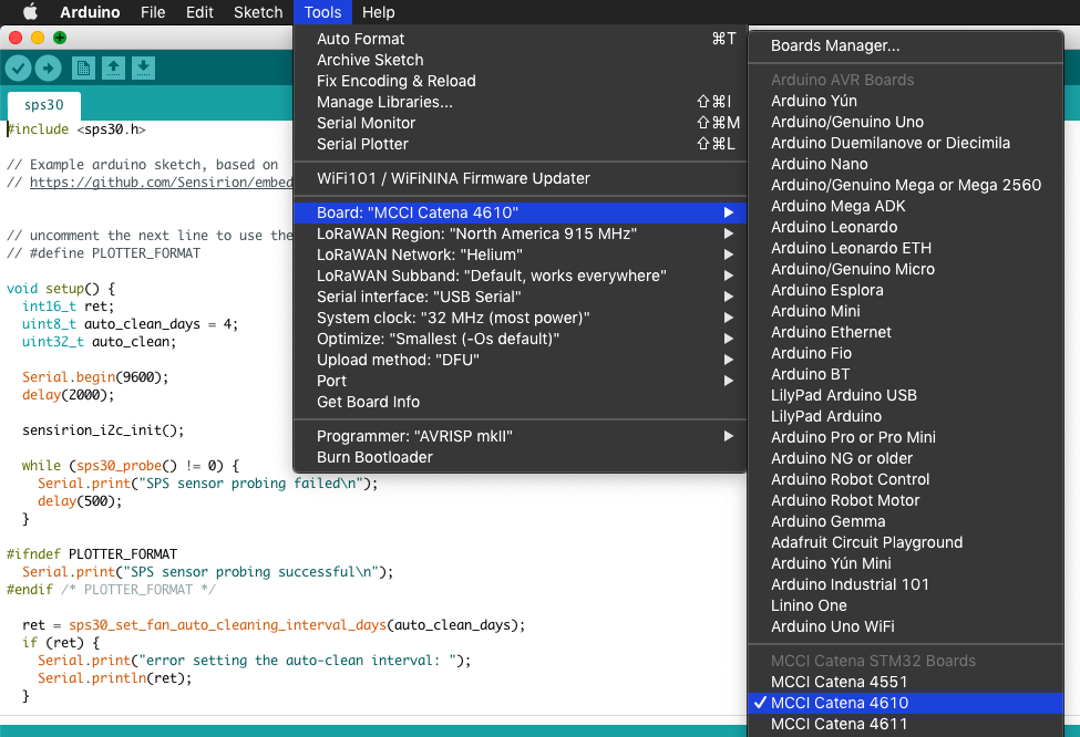
6.) On the toolbar at the top, click Tools, then select "Board: " (it will have some type of option for an Arduino board), then select "Boards Manager..."

The Boards Manager menu will pop up. In the search bar, type "catena" and two options should appear.

Note: you want the option for the STM32, because that's the processor on the Catena 4610 board. If you're using a different board, check the processor and use that to choose your option.
7.) Click Install. When the install finishes, you may close the Boards Manager menu.
Add the library for the SPS30 to the Arduino IDE
1.) We next want to add the library for the SPS30 sensor. On the Arduino IDE toolbar at the top, click Tools, then select the "Manage Libraries..." option. This opens the Library Manager menu.

In the search bar, type sensirion-sps. Install the library that appears. Click close when done.

Upload the Sketch to the Catena Board
1.) Open the example sketch. On the Arduino IDE toolbar, click File, then select the Examples option. Scroll (if necessary) to the sensirion-sps option, and select sps30. This opens the example sketch for the SPS30.

2.) Select the correct board. On the toolbar, click Tools, select the "Board: " option, and click the MCCI Catena 4610 option.

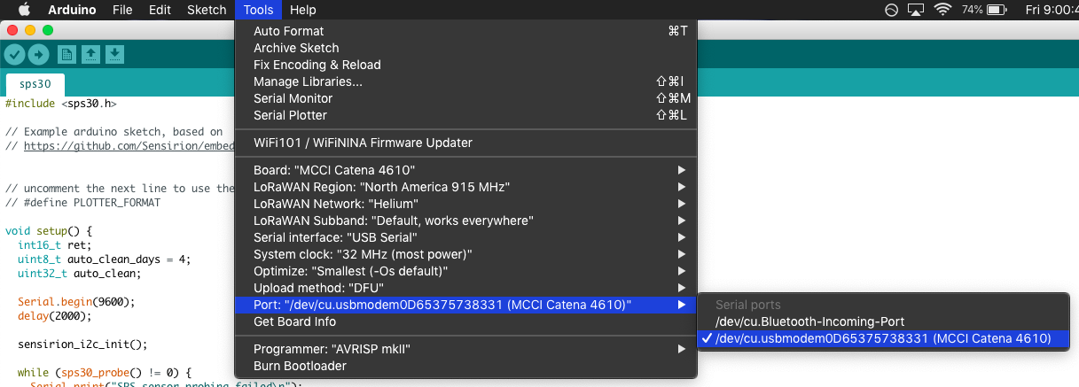
3.) Make sure the Arduino IDE detects the board. Plug-in the Catena board via USB if you have not already done so. On the toolbar, click Tools, select the "Port: " option, and click the option that appears for the Catena board.

4.) Put the board in DFU mode. DFU stands for Device Firmware Update. Put the board in DFU mode by holding down the boot button and clicking the reset button on the board. The board will indicate it is in DFU mode by changing its LEDs.
5.) Click upload. It may take a few seconds for the board to program; the Arduino IDE will indicate when it is complete.
Connect the Sensor to the Catena Board
How you connect the sensor will depend on the details of your hardware, such as if you have headers soldered to the Catena, etc. Therefore, the best way to share information is to list the signals coming from the sensor, and where they should connect on the Catena 4610.
Here is a diagram showing the physical pin numbering on the SPS30:

And here is the pinout:

Here is a table showing the signal connections between the SPS30 and the Catena 4610:

Helpful note: the (unpopulated) screw terminal headers on the Catena 4610 each have a GND pin


Here is a picture showing how I soldered those connections:

Test Your Setup!
Open your serial monitor, and you should see something like the following!

Helpful Troubleshooting Tips
Here are some helpful starting points for troubleshooting your sensor:
- Verify the SPS30 is getting 5V. The VBUS pin is directly connected to USB power, which provides 5V.
- If you are running off a battery, you will need to derive the 5V supply elsewhere.
- Verify that SEL is being pulled to GND. This selects the I2C interface on the sensor.